Dave Smith Instruments Prophet '08 — Encoder replacement
Table of Contents
The Dave Smith Instruments Prophet ‘08 is a modern classic, an 8-voice, 16-oscillator powerhouse that brought the Prophet name back to the forefront of analog synthesis, honoring the iconic Prophet 5.

However, even the best designs can have an Achilles’ heel. If you own an early Prophet ‘08 or even its renewed PE version (Potentiometer Edition), you’ve likely encountered the dreaded “erratic values” when moving the encoders on the front panel.
The factory-installed continuous encoders are notorious for oxidation. Over time, the internal contacts degrade, leading to jittery values that make precise sound design an exercise in frustration. Or even impossible! Today on the bench, we are performing something more than a simple repair. I would define it a full “organ transplant” — replacing every single factory encoder with high-quality stepped alternatives.
To understand the issue, we have to do a quick detour on how digitally controlled analog synthesizers manage front panel reading and controls. Two main architectures are usually implemented:
- Potentiometers as voltage dividers — each control on the front panel is a linear potentiometer; the voltages present at each wiper are buffered, sampled at regular intervals by an ADC, stored by the CPU, converted back to analog voltages by a DAC and used as Control Voltage (CV) sources for all sections of the synth (an in-depth analysis on this architecture will be on a future read, when we will be working on the Moog SubPhatty).
- Rotary encoders — and since this is the case for the Prophet ‘08 on the bench today, let’s dive.
How encoders work #
Unlike a potentiometer, an encoder does not output variable voltages depending on its absolute position, but it works by sending precisely timed pulses depending on the direction of rotation. This principle is called Quadrature Encoding. The rotary encoder can be seen as two switches (called Channel A and Channel B) that open and close in sequence as you turn the shaft.
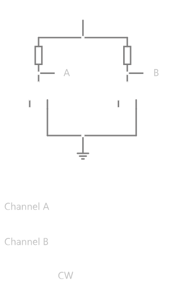
The switches, closing, connect the input voltage to the outputs, generating signals that are \(\pm 90^\circ\) out of phase. Phase is positive when turning clockwise and negative when turning counter-clockwise. The CPU monitors the state of both channels to determine the direction of the turn:
- Channel A leads Channel B: increment the value in memory.
- Channel B leads Channel A: decrement the value in memory.
When oxidation occurs on the internal contacts, the “pulses” become electrically noisy, technically they bounce. The CPU, instead of seeing precise and sharp pulses, sees a chaotic series of state changes, which it interprets as the parameter jumping wildly back and forth.
Parts #
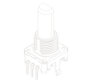
For this upgrade, I have selected the Alps Alpine EC12E series. These are superior to the factory parts due to their higher rotational life and better sealing against oxidation. I specifically chose the version with the 20mm bushing (longer than stock) to provide better mechanical robustness and stability to rotation.
| Model Variant | Quantity |
|---|---|
| Prophet ‘08 (Standard) | 52 |
| Prophet ‘08 (PE Edition) | 11 |
Replacement Procedure #
Disassembly & PCB Extraction #
The initial stage of the process involves removing all front panel knobs and chassis screws. Once the front panel is opened, the internal ribbon cables are disconnected, followed by the removal of all mounting screws securing the front panel PCBs.
During the extraction of the front panel PCBs, caution is required because the plastic button covers can be loose and easily lost.
“Snip and Pull” Removal Method #
Since the original encoders are destined for the scrap heap, there is no need to struggle with desoldering the entire multi-pin component at once.
Instead, the process involves using a sharp flush-cutting tool to snip every leg of each encoder. Once the main bodies of the encoders are cleared away, flux is applied to the remaining pins, which are then cleared out using either desoldering braid and a tweezer or a desoldering gun. The larger structural side tabs are subsequently removed using fine tweezers and a standard soldering iron.
Resoldering and reassembly #
The next phase involves populating all vacant positions on the board with the new encoders and soldering each one to the board.
The front panel PCBs are then reassembled to the metal frame, again paying attention to the plastic button covers in order to insert all of them correctly, and the whole physical housing of the synthesizer is finally reassembled.
Final system settings #
The final step requires modifying the internal software configuration settings to match the new hardware:
- Power on the synthesizer
- Enter Global Settings.
- Change the EncMode parameter from Non-Det to Detent

The Aftermath #
The “organ transplant” is a complete success. Here the pile of removed parts.

And here the fully resoldered boards with all the brand new 24-detent encoders. A machine brought back to life and a very happy knob fiddler.


If your own early-generation Prophet is sitting in a corner gathering dust due to jittery encoders, this upgrade is well worth the bench time — it breathes decades of new life into a modern analog classic.